Scoping candidate
MV SiC characterisation & DPT
Turn switching losses, overshoot and stability into a measured basis for the next design decision.
Read the introduction → ×

21 assessed tracks
Testing, characterisation, modules, packaging and the technical backbone that enables design-in.
Scoped studies, characterisation, failure analysis, co-design, reference designs and validation plans.
The DOE draft treats materials, devices, packaging and system integration as interdependent parts of wide-bandgap power-electronics development.
U.S. DOE · Draft WBG Strategic Framework, Jan 2025 ↗Turn switching losses, overshoot and stability into a measured basis for the next design decision.
Read the introduction →Find the cause of recurring field failures before the next hardware revision enters production.
Read the introduction →Give development tracks accountable commercial and operational leadership from customer problem to funded decision.
Read the introduction →Help a module manufacturer turn packaging knowledge into a repeatable process and a better design.
Read the introduction →Reduce oscillations and EMC issues by co-designing the driver, layout and switching cell.
Read the introduction →Turn repeated MV testing engagements into a configurable test cell for selected laboratories.
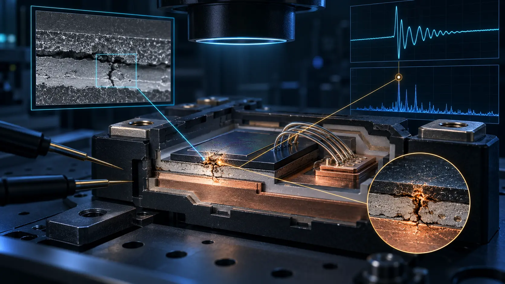
Read the introduction →Document lifetime and degradation under thermal and electrical stress to support an OEM qualification decision.
Read the introduction →Find power-stage, thermal and stability problems before expensive external qualification.
Read the introduction →Explore whether multiple customers can share specialised packaging infrastructure and expertise.
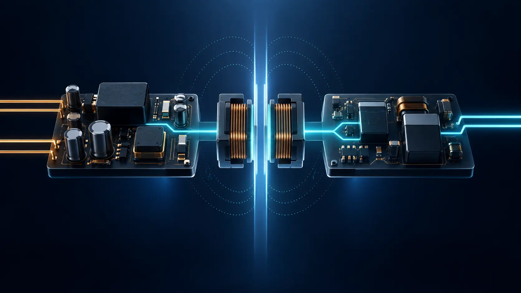
Read the introduction →Investigate an isolated auxiliary supply for a gate driver in a 10 kV module environment. The 15 W nominal power target requires validation alongside insulation and coupling capacitance.
Read the introduction →Make it easier for an OEM to evaluate a validated solution in its own switching cell.
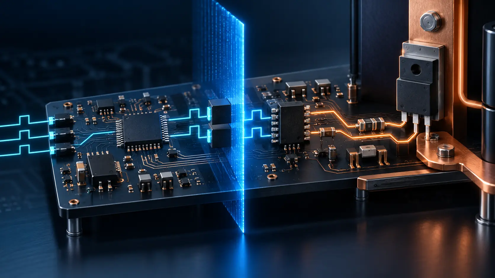
Read the introduction →Develop the driver architecture around the actual SiC switch and system protection requirements.
Read the introduction →Package a validated auxiliary supply in a format that is easier to integrate in laboratories and installations.
Read the introduction →Adapt the isolated supply to specialised floating and high-voltage environments.
Read the introduction →Explore new medium-voltage converter possibilities through module and packaging development.
Read the introduction →Explore whether stabilisation can be integrated into an OEM module design to create a licensable advantage.
Read the introduction →Scale current and power by making parallel modules operate stably together.
Read the introduction →Shorten integration work with module and gate-drive models that can be compared with measurements.
Read the introduction →Explore stability and integration in press-pack-based power systems.
Read the introduction →Make the module and reference design a scoped building block in the OEM converter.
Read the introduction →Create a shared control platform when it makes an active hardware engagement faster and more testable.
Read the introduction →Detailed assumptions, financial scenarios and internal review material are preserved on the access-controlled internal site.
NEXT STEP
Tell us about the system, the specific challenge and the decision you need to make. We can then scope a relevant technical and commercial study.
The links open your email client. Requests for materials are reviewed individually; access is not automatic.